
- #Arduino pwm servo example full#
- #Arduino pwm servo example code#
- #Arduino pwm servo example download#
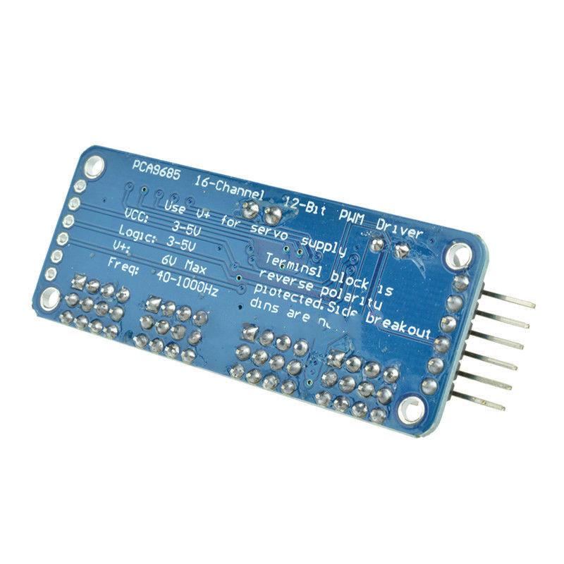
Mine currently has 1,000uF and struggles to keep 8 Servo in sync. (if it hasn't got one, get one) I recommend the bigger the better. (each servo under load, can peek over 1 Amp)Īlso most breakout boards I have seen come with a capacitor. I recommend having a separate voltage supply for the PCA9685 V+ power (No. (if just powered of the USB, there will be a voltage drop of about 1.5v through the voltage regulator) If you are using power from the Arduino, don't have the Arduino power just by a USB, have at least 9 volt powering it on the power VIN. It's actually it is 8 bit but you don't see the first or last bit) Top right as shown in photo, there are six solder able links that can be soldered to change the address of the PCA9685, should more than one be connected. OE Output Enable (making this Logic High, disables the PWM).GND Ground (negative power connection).(The same connections are repeated at the opposite end of the board, to make it easy for daisy chaining) The PCA9685 Breakout Board has six connection. So I decide to make an application to make things simple, and help find each Servo setting required and be able to run sequences (script) to test commands sent to the servo.
#Arduino pwm servo example code#
Writing and re-writing code to see what happens, can be quite a pain. Setting up eight servo, finding the trim setting for each, determining there max. (we start simple, in theory my app can control 1024) Now having a project that has many Servo to control, lets say a four legged robot. That totals 1024 number that can be controlled from one Arduino. The PCA9685 communicates via I2C and has 64 possible address, this means that 64 of these devices can be daisy chained one after the other, each with 16 servo or LED attached to each. The PCA9685 LED controller although designed to control LED's, can be configured to control Servo.

#Arduino pwm servo example full#
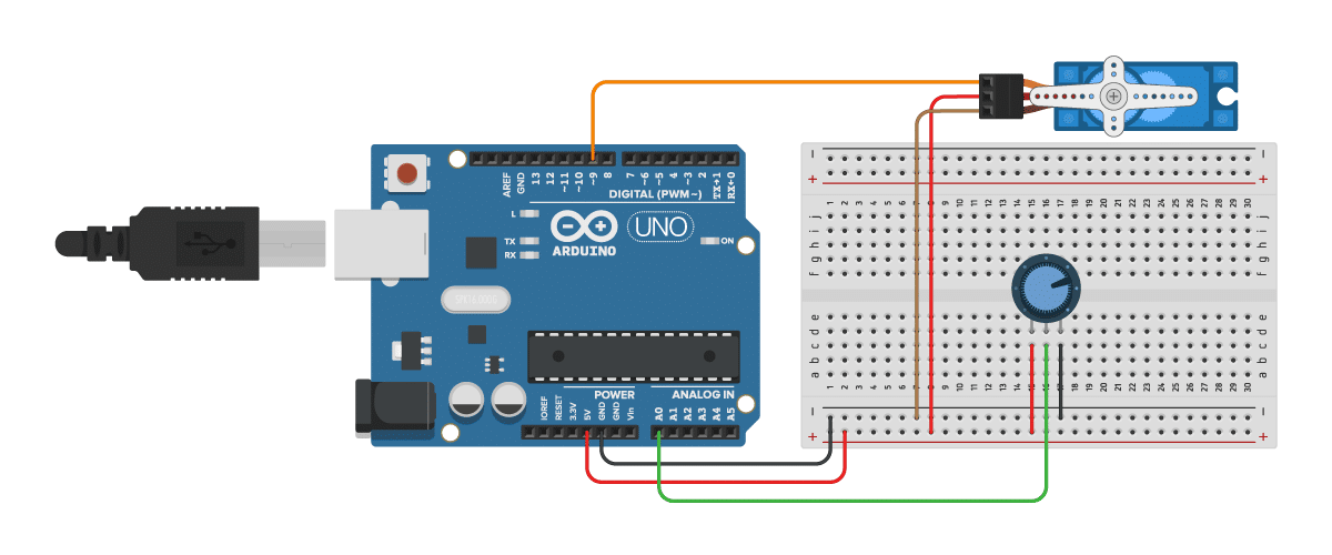
If using only one or two servo, these can be controlled direct from an Arduino using a library and allocating pins to do this.īut for projects needing many servo to be controlled, the (lets give it its full name) PCA9685 16-channel, 12-bit PWM Fm+ I2C-bus LED Controller, may be the better choice. void loop(void)įor (float dut圜ycle = 30.0 dut圜ycle < 100.Many projects done with the Arduino, involve using a Servo. In the loop, we increase the duty cycle from 30% to 100%, in steps of 1% in a for loop. In the setup, we initialize the Timer1 library at 40 microseconds interval (or 25 kHz frequency), and we also initialize Serial. We include the library and begin with specifying the fan pin. Over here, the speed of the fan, connected to pin 4 (you need to change it to pin 9 or 10 for Arduino Uno), is changed using PWM. You can also find the code on GitHub here − Go to File → Examples → TimerOne → FanSpeed We will look at the example that comes with the TimerOne library. Thus, if you want a frequency of 100kHz, you set the microseconds time as 10. Where the argument is the microsecond interval of the wave. We do that in the setup, using the Timer.initialize() function. You may be wondering where did we set the frequency of the PWM. If you wish to change the duty cycle mid-execution, you can use − tPwmDuty(pin, duty) Īnd to disable PWM, you can use − Timer1.disablePwm(pin) 0 represents a duty cycle of 0%, while 1023 represents 100%.

Only pins 9 and 10 allow Timer1 based PWM.ĭuty is the duty cycle (from 0 to 1023). Where pin is the pin number on which you wish to set the PWM.
#Arduino pwm servo example download#
Go to Tools → Library Manager, and download the TimerOne library. This is based on the TimerOne library that we have seen in the past, in the article concerning Timer Interrupts in Arduino. The advantage of this method is that it allows us to control the frequency of the PWM signal as well, along with the duty cycle. In this article, we will look at another way of setting PWM in Arduino Uno, specific to Timer1. With analogWrite() you get control over the duty cycle, but not on the frequency of the generated square wave. The frequency of the square wave is 490 Hz (about 2 ms time period) on all pins except 5 and 6, on which it is 980 Hz (about 1s time period). Pins 3,5,6,9,10 and 11 of Arduino Uno can support PWM. In an earlier article, we have seen how PWM can be set on Arduino Uno using the analogWrite() function.


 0 kommentar(er)
